Take-up Lever replacement
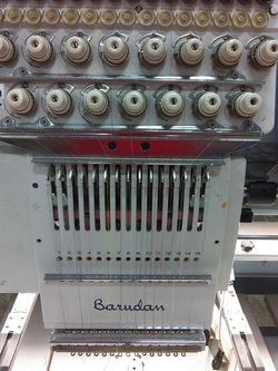
Make/Model- Barudan BEVS-Z1515C
Issue- Multiple Broken Take-Up Levers Cause- Unknown Time- est. 45min- 1.5 hrs |
Step 1- Remove the Cover
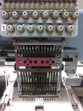
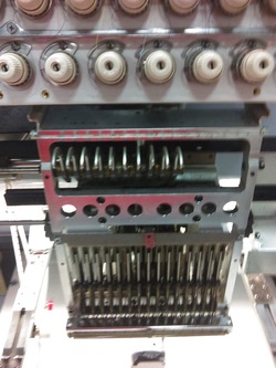
First thing we want to do is tie off the thread right below the top-tension springs and cut the remainder. Now that it's loose we can unscrew the lower two phillips head screws and remove the two top chrome/silver thread guide brackets. Now you should have a head that looks something like this one on the left. |
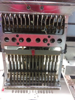
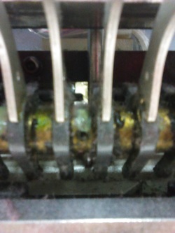
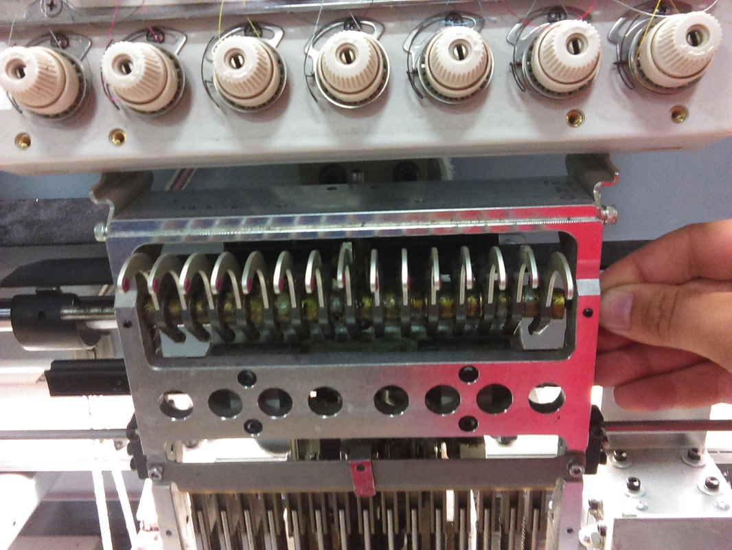
As we remove the cover we now see the exposed guts of the head. This is a good time to inspect your driver, cam, pins and so on. This head in particular hasn't been cleaned in a long time, so we notice the build up of grease and fuzz. When we remove this section of the head we will have the opportunity to clean behind the levers as well, so right now let's move on.
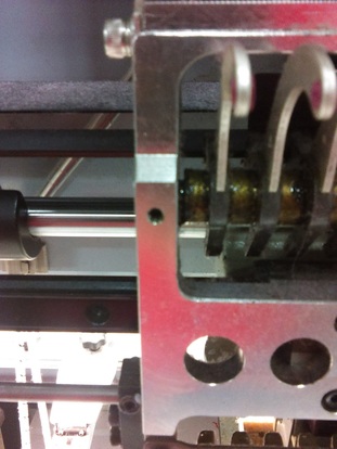
Here we have a set screw on both the left and right sides of the alum-cast head. Do NOT take them all the way out. Just a few CCW turns will do
|
|
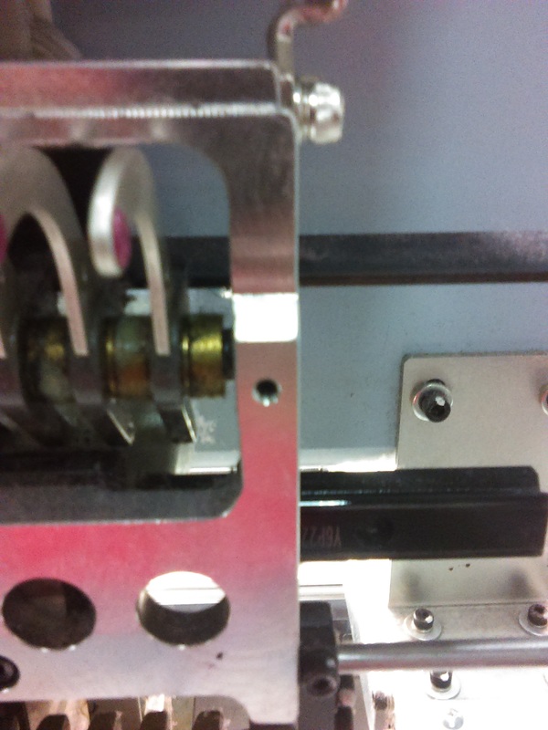
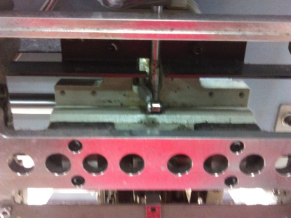
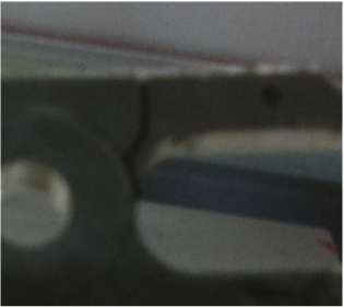
Notice how the far right bushing (bronze/gold) is smaller than the one next to it? Keep this in mind throughout the repair.
|
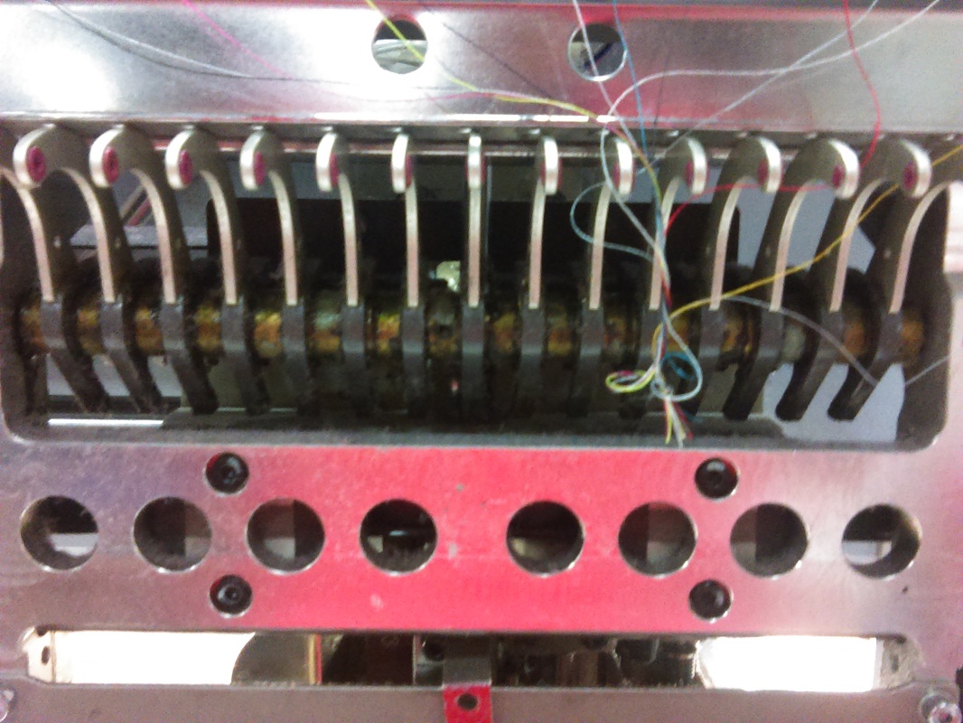
Step 2- Loosen Set Screws
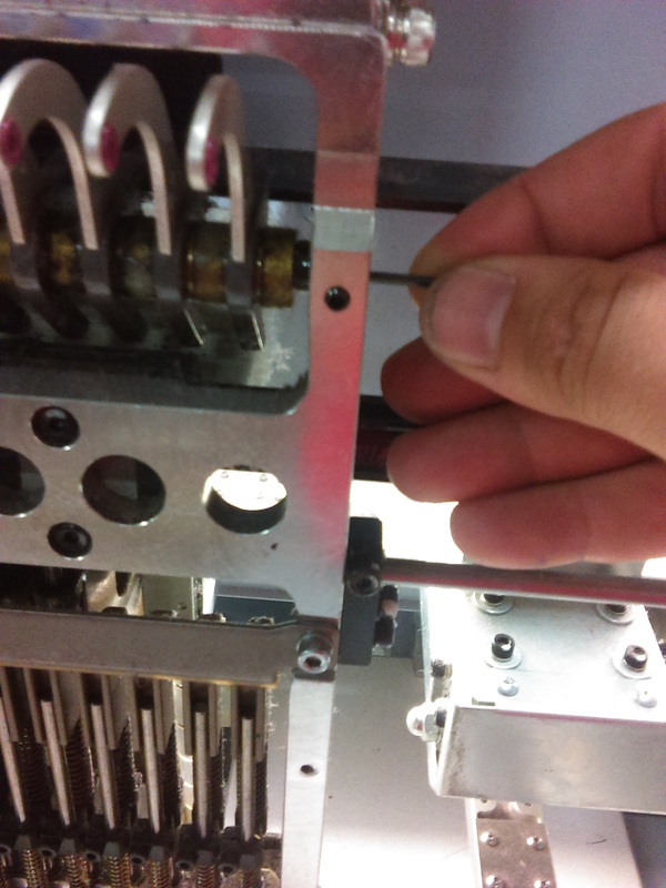
There are 3 Set Screws you need to loosen to remove the Take-Up shaft. Remember just to loosen them, if you accidentally take them all the way out it is gonna be a booger to put back in. *Important- Always count how many levers are to each side of the middle set screw. In this case it's 7-left and 8-right. |
|
Step 3- Remove Shaft
Here we want to use some kind of small rod (end of allen-wrench) to slowly push out the lever rod. As you push more of the rod out, grab the bushings and levers. Do this until all the pieces are out. *Note- You may need to pull out the black compression sleeves ( between the alum-cast frame and rod) to be able to swing the rod enough to clear the other head for removal.
Here we want to use some kind of small rod (end of allen-wrench) to slowly push out the lever rod. As you push more of the rod out, grab the bushings and levers. Do this until all the pieces are out. *Note- You may need to pull out the black compression sleeves ( between the alum-cast frame and rod) to be able to swing the rod enough to clear the other head for removal.
|
At this point we want to collect ourselves and check to see if any pieces might have fallen inside the head. I can't tell you the number of times stuff gets lost in there. Is everything accounted for?
Good let's move on. 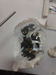
As we remove the levers we can decide whether or not the bronze bushings need to be replaced. BUT 9-times out of 10 they just need to be clean up a bit.
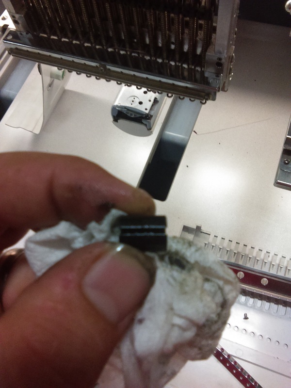
Picture on the Left is of the compression sleeve from Step 3. |
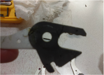
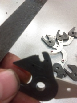
We had 7 levers that needed to be replaced. Question now is 'What caused this to happen?' As you can see in the picture above the fracture on the lower arm ( it would be the top in this picture because it's held upside down).
Inspect all elements of the repair and decide which ones to keep and which ones to replace. *It's sometimes cheaper just to throw a iffy one away and replace it than spending TIME trying to make repairs to it. |
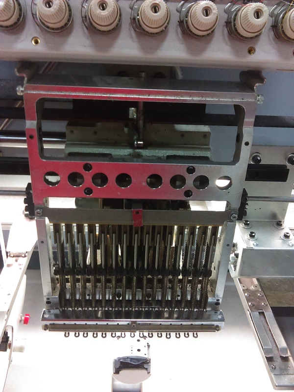
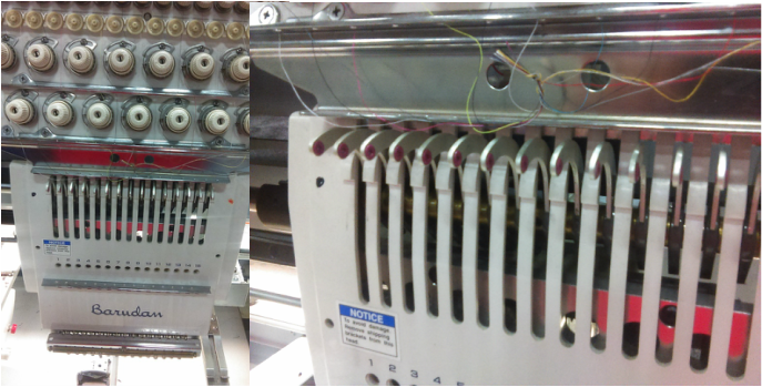
Step 4- Inspect the Head
Here at this point we have removed the Take-Up Levers, spacers and shaft. In this case several of the levers were actually broken so we need to look for any pieces that may have fallen into the head.
|
|
This small crack is all it needs to make a mess of thread. You can check the levers by changing the needle to that specific one and using your index finger and thumb try moving the lever. Does it move too much? Does it have a clicking sound? These are good indicators that you have a broken lever.
|
Time for the Spit Shine
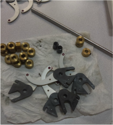
Gather all your good parts as well as the new ones and give them a good cleaning. That caked up grease can cause a mess of problems for you. Use some sort of parts washer or cleaner and prepare for the install. |
Step 5- Prepare for Reassembly
As you can see in the picture to the left, there is some small nicks and rough spots on the re-usable levers. Simply use a small fine file and work away the "burrs" or the imperfections. Next, go ahead and spray a little lube ( LB5- preferably) inside the levers and bushings. REMEMBER that you have 2 smaller bronze bushings, one with a set screw and those 2 black compression sleeves. All of this needs to sprayed down and it's a good idea lay them out into piles. I can't explain enough how horrible it is for you to get the lever assembly almost completely installed and realize you have too many levers on one side of the set screw or you place the larger bushing on the outside and now you gotta remove the shaft and line it back up again.
I'm just saying it's better to be prepared than in a hurry...

Step 6- Reassemble
One this step it is important to stay patient and take it one piece at a time. Remember to put the compression sleeve in one side and start sliding the shaft into the guide hole. * NOTE- The small bushing comes first THEN the lever.
On the back-side of the levers you want to slide them onto the railing and gently push the rod through the lever. It is a lot easier to hold the lever and push the rod than it is to push the lever onto the rod while holding it to the guide rail.
Slowly work the levers and rod until you get to the center bushing with the set screw. (DO NOT Tighten yet) Reconfirm that you put it on just as you have taken it off. In my case 7 on the left and 8 on the right. This is a ZQ head type, which means 15-needles. On most occasions the process will be the same no matter how many needles you have.
After installing all 15-take-up levers and bushings, pass the rod through the other side of the alum-cast head. (You might want to leave the last compression sleeve out for now). ****IMPORTANT: MAKE SURE THAT THE CORRESPONDING LEVER TO WHICH EVER NEEDLE YOU ARE ON IS LOCATED CENTERED ON THE TAKE-UP LEVER DRIVER ASSEMBLY.
Now once you have everything set properly, insert the compression sleeve and tighten both the OUTSIDE SET SCREWS first. Re-check to make sure you are lined up on the driver assembly and then tighten the center bushing set screw. At this point you want to confirm that there is very little movement left-to-right in the take-up lever assembly. In some cases you might need to slide the compression sleeves inward towards the bushings to get a tighter fit.
Step 7- Final Touches
It is very important at this moment to check and re-check your work. Believe me you don't want to get it all put back together just to have to remove it because you forgot to tighten a screw or you just realized that you wanted to clean behind the lever assembly.
Once you are satisfied with the job, go ahead and let's put the cover on.
First start with the top two chrome thread guide brackets. At this moment we just want to loosely attach both pieces so we can slide the face plate on. **Now is a good time to spray lube the take-up bar assembly** Slide the face plate cover under the thread guide bracket and put on the lower thread guide which attaches directly to the plate. Screw both the bottom phillips head screws in while alternating from each one until it becomes tight. We do this just to insure that it lines up before we crank one down. Once that's installed you can tighten both the top brackets in the same fashion.
All tight? Now gently press each of the finger-like pieces on the top of the plate inward and have them seat behind the chrome bracket. You should feel them kind-of "click" in. Once again I stress that you check your work.
Once everything is back to normal, minus the thread being threaded, go to the automat and change needle from 1 to 15 a couple of times. This will ensure that the backs of the levers are securely on the rail from the earlier step, as well as confirm that the driver lever assembly slides through the levers without any friction. * We still haven't confirmed how the original levers broke yet, but now is a good time to see if they bind or hit something it's not supposed to. Now that we know everything is in working condition we call it fixed, have an operator help you thread the head and run some test stitches.
|
This my friend is 'How to replace a take-up lever'
If you have any questions or comments on this Repair Help please let us know by emailing us @ [email protected]. We will be more than happy to assist you in any way we can. So once again thanks for choosing Sew-Sweetly Embroidery for you embroidery go-to guys. |
|
